Ink Geometry Pipeline & Rendering
In general, the engine differentiates between raster particle - called Raster Ink - and vector polygon rendering - called Vector Ink - with the main differences listed in the table below. The geometric primitives computed by the Ink Geometry Pipeline are paths containing control points that are interpolated using a Catmull-Rom spline. In addition to the control points, the stroke mathematical model specifies the values of the interpolation parameter in the first and last segments, in which the stroke starts and then ends, respectively. If required, all paths can be created with variable width and opacity. The rasterization techniques that are implemented in the Rasterizer module are techniques for stroking paths that have these characteristics.
| Raster Ink | Vector Ink |
|---|---|
 |  |
| Fixed resolution - defines the graphic on pixel level | Scalable and portable - suitable for printing or displaying on various devices |
| Enables pixel level manipulations like smudge | Object model - can be manipulated with various geometry operations |
| Greater flexibility in terms of expressiveness | More complex for rendering and more limited expressiveness |
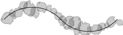
Vector Ink (shape-filling technique) is a solid color technique for rasterizing strokes that have variable width. This method is more limited in terms of expressiveness, but performs better than more complex rendering techniques. It is suitable for typical scalable vector graphics usages or handwriting applications. Because of its simplicity in terms of expressiveness, strokes that are rasterized with this technique can be easily manipulated (split), scaled, redrawn, and so on (see Figure 1).
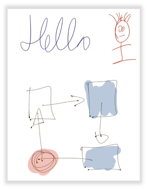 Figure 1: Vector example.
Particle Ink renders strokes using overlapping particles. This technique allows you to build more expressive tools (such as crayon, pencil, or watercolor brushes) by controlling several rendering parameters described in the rendering section. It is focussed on semi-professional drawing applications as illustrated in Figure 2.
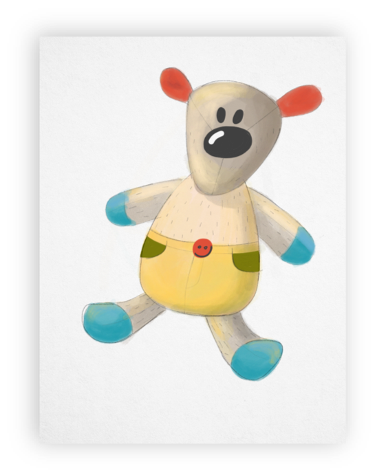 Figure 2: Raster example.
Pipeline
In computer graphics, a rendering pipeline, is a conceptual model that describes what steps a graphics system needs to perform to render objects. For the WILL ink rendering, this process is split into the geometry pipeline, which is implemented for all platforms in the same way; and the rendering part, which utilizes the platform-specific graphics frameworks.
In the application the geometry pipeline is created and configured in the InkBuilder.
The VectorInkBuilder extends the pipeline for vector brushes, while RasterInkBuilder is specialized for raster (particle) brushes.
WILL 3 uses a geometry pipeline, consisting of a chain of processing blocks (processors, producers, etc.).
The input of the pipeline is pointer data (touch, stylus, mouse, or controller), which passes through a set of processing stages.
The output of each stage is taken as input by its successor.
The main goal of the pipeline is to create digital ink.
However, its generic implementation allows a much broader set of capabilities.
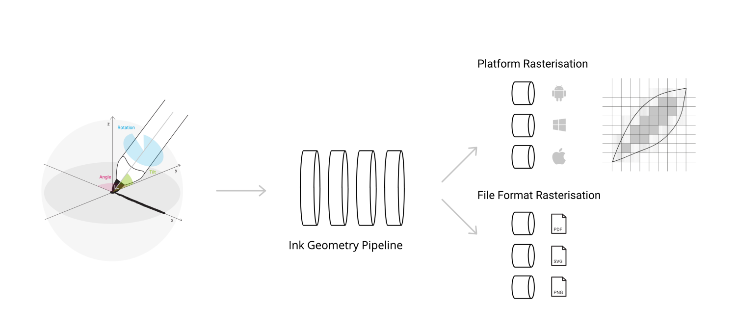
Figure 3: Rendering pipeline for WILL 3.
Input
The best input provider is a pen, as it provides the most sensor input and is the most natural device for writing or sketching.
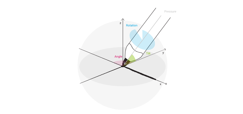 Figure 4: Overview ink sensor channels.
The following input is available:
- Position - Defined by x and y coordinates - the position of the input point
- Phase - The phase of the input (Begin, Update/Move, End)
- Timestamp - The timestamp of the input, used to calculate velocity
- Force - OPTIONAL - (pressure) The value reported by a pressure sensitive stylus/display
- Radius - OPTIONAL - The size of the touch input
- Altitude Angle - OPTIONAL - The elevation angle (OE) between the input device and plane of writing. Measured in radians - between 0 and π/2
- Azimuth Angle - OPTIONAL - The angular distance along the plane of writing to the location of the object
By convention, azimuth (OA) is measured from the top towards the bottom (north towards south) along the plane. Measured in radians - between 0 and 2π (see Figure 5).
 Figure 5: Azimuth diagram.
Internal Representation and Models
-
Pointer Data - (Input Data/Touch Data) - The input in the format described above
-
PathPoint - The internal representation of point
-
Path - Flat set of PathPoints (see Figure 6), each of which is computed by calculator, which can either be predefined, or passed from outside:
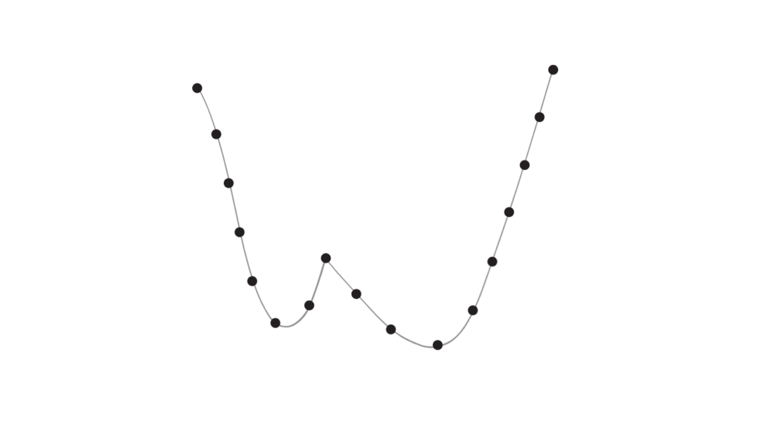 Figure 6: Path points.
-
Layout - The descriptor of the items in each path point
-
Spline - Centripetal Catmull-Rom spline (see Figure 7), defined by its control points:
 Figure 7: Catmull-Rom spline.
- Point Set - A set of points that defines a filled area with specific form (not just a point). The technology uses a simple brush that is defined by its hull and not by a point set.
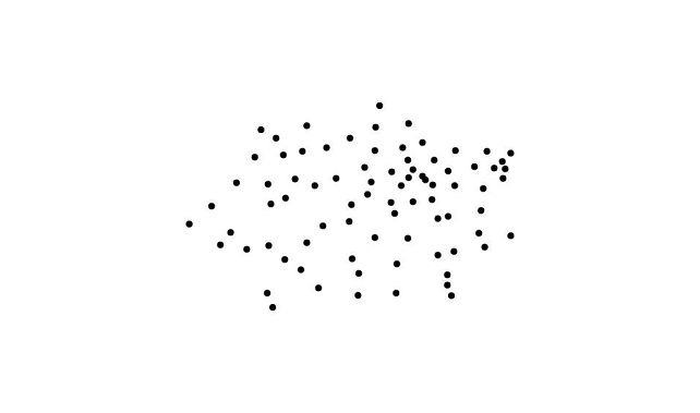 Figure 8: Point set.
- Polygon - Polygons are created from Point Sets using convex-hull.
The polygon is
Collection<DIPoint2>:
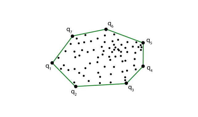 Figure 9: Polygon points.
Data Classes:
DIPoint2- 2D point with x and y coordinatesDIPoint3- 3D point with x, y and z coordinatesDIPoint4- 3D point with x, y, z coordinates and widthDIPointList2D-Collection<DIPoint2>DIPolyline-Collection<DIPoint2>
Processing blocks
The pipeline consists of a chain of processing blocks (processors, producers, etc.).
The following illustration visualises the processing blocks and provides examples of intermediate steps.
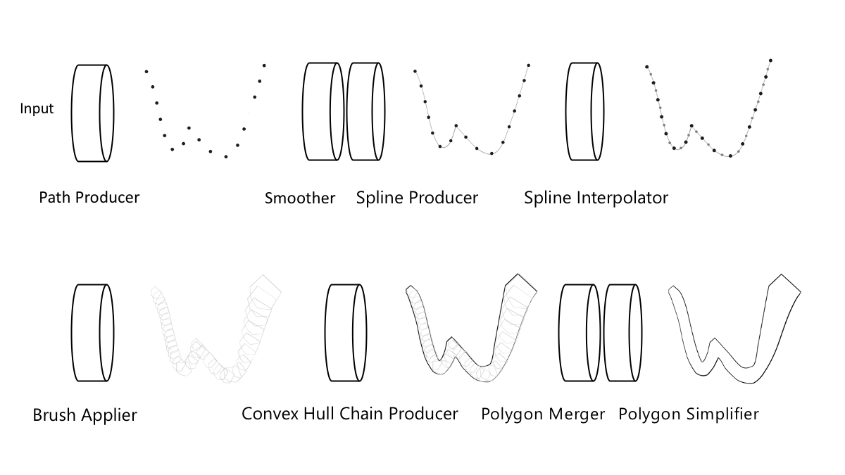 Figure 10: Pipeline and its intermediate results.
BaseDataProcessor
The abstract base class DataProcessor for pipeline stages that process data based on a single input item.
It defines two abstract methods:
add(phase: Phase, addition: Input, prediction: Input): Pair<Output, Output>- Inputs stroke data in the pipeline stage and processes itreset()- Resets the processor to its initial state
PathProducer
Converts the input into internal path representation based on the supplied layout.
Constructor Parameters (wrapped into a Config class):
- Layout
- Calculator - Function that converts the input into
PathPoint
Add parameters:
- Addition - InputData - The input which we want to process
- Prediction - InputData - A prediction for a future input
Output:
- Addition -
Path as Collection<Float> - Prediction -
Path as Collection<Float>
Smoother
Makes the path smoother via Double Exponential Smoothing. A negative result of the smoothing is that the result lags with one point.
Constructor Parameters:
- The size of the layout (used as stride for processing the input)
Add parameters:
- Addition -
Collection<Float>- the path generated by theTouchToPathProducer - Prediction -
Collection<Float>- the prediction path generated by theTouchToPathProducer
Output:
- Addition -
Path as Collection<Float> - Prediction -
Path as Collection<Float>
SplineProducer
Adds two control points, one in the beginning and one at the end of the path, in order to produce a Catmull-Rom spline.
Constructor Parameters:
- The size of the layout (used as stride for processing the input)
Add parameters:
- Addition -
Collection<Float>- The path - Prediction -
Collection<Float>- The prediction path
Output:
- Addition -
Spline as Collection<Float> - Prediction -
Spline as Collection<Float>
SplineInterpolator
Discretizes the spline by adding points along its trajectory, spaced out according to the spacing parameters.
Constructor Parameters:
- Layout
- Spacing - The spacing between two consecutive as a multiplier (fraction if below 1) of the size
- Split Count - The amount of splits
Add parameters:
- Addition -
Collection<Float>- The spline - Prediction -
Collection<Float>- The prediction spline
Output:
- Addition -
Spline as Collection<Float> - Prediction -
Spline as Collection<Float>
BrushApplier
Converts the spline into a collection of point sets by replacing the points with brush polygons.
Constructor Parameters:
- Layout
- Brush Polygon - The polygon that defines the brush
Add parameters:
- Addition -
Collection<Float>- The spline - Prediction -
Collection<Float>- The prediction spline
Output:
- Addition -
Collection<DIPointList2D> - Prediction -
Collection<DIPointList2D>
ConvexHullChainProducer
Creates a convex hull around each two consecutive point sets, using the monotone chain algorithm.
Add parameters:
- Addition -
Collection<DIPointList2D>- The collection of point sets - Prediction -
Collection<DIPointList2D>- The prediction collection of point sets
Output:
- Addition -
Collection<DIPolygon> - Prediction -
Collection<DIPolygon>
PolygonMerger
Merges polygons using Union. Uses the Clipper library and its respective ports in the different platforms.
Add parameters:
- Addition -
Collection<DIPolygon>- The collection polygons generated by the ConvexHullChainProducer - Prediction -
Collection<DIPolygon>- The prediction collection polygons generated by the ConvexHullChainProducer
Output:
- Addition -
Collection<DIPolygon> - Prediction -
Collection<DIPolygon>
PolygonSimplifier
Takes the curve composed of line segments (polygons) and finds a similar curve with fewer points, using the Ramer-Douglas-Peucker algorithm.
Constructor Parameters:
- Epsilon- Threshold value that determines the level of simplification. Greater values result into polygons with fewer segments.
Add parameters:
- Addition -
Collection<DIPolygon>- The collection simplified polygons - Prediction -
Collection<DIPolygon>- The prediction collection simplified polygons
Output:
- Addition -
Collection<DIPolygon> - Prediction -
Collection<DIPolygon>
Rendering
Rendering of the result of the pipeline is done by using each platform's specific 2D rendering APIs, and for particle rendering platform graphics engines, such as:
- DirectX is used in the Windows 10 UWP / WPF implementation
- OpenGL for raster rendering and Android Canvas (2D API) for vector
- Metal is used for raster rendering on iOS, while the vector rendering is using Core Graphics
- WebGL is used for our Web technology
Platform-specific vector rendering
In most cases, Bezier curves are used as path objects, which can be created easily by connecting the vertices of the polygons produced by the pipeline. The result of this is a filled Bezier contour, representing the path.
The PathPoint Calculator
The calculator is a method that you pass to the PathProducer stage.
It defines how data from pointer events is transformed to path points.
Our sample applications have three example path point calculator methods: one in VectorInkBuilder and two in RasterInkBuilder (one for pen input, one for mouse).
Building Ink
In order to use the pipeline, you need to create a data layout that specifies the content of the ink paths. Here is a basic layout where path points have X, Y coordinates and variable size. Potential properties are:
PathPoint.Property.X- X coordinatePathPoint.Property.Y- Y coordinatePathPoint.Property.Z- Z coordinatePathPoint.Property.RED- Red color valuePathPoint.Property.GREEN- Green color valuePathPoint.Property.BLUE- Blue color valuePathPoint.Property.ALPHA- Alpha color valuePathPoint.Property.SIZE- Size value associated with the path pointPathPoint.Property.ROTATION- Rotation value associated with the path pointPathPoint.Property.SCALE_X- X dimension scale value associated with the path pointPathPoint.Property.SCALE_Y- Y dimension scale value associated with the path pointPathPoint.Property.SCALE_Z- Z dimension scale value associated with the path pointPathPoint.Property.OFFSET_X- X dimension offset value associated with the path pointPathPoint.Property.OFFSET_Y- Y dimension offset value associated with the path pointPathPoint.Property.OFFSET_Z- Z dimension offset value associated with the path pointPathPoint.Property.D_X- Tangent vector X valuePathPoint.Property.D_Y- Tangent vector Y value
To build ink in real time, you need to handle pointer input events OnPointerPressed, OnPointerMoved, OnPointerReleased and provide input to the InkBuilder.
The InkBuilder passes the pointer input data to the first pipeline stage - the PathProducer.
The output of the PathProducer is accumulated, because more than one input point can be received between two frames.
The sample application uses the PathSegment helper class in order to accumulate the path parts.
The accumulated path is then passed through the rest of the pipeline stages.
The output of each stage goes to the input of the next one.
Each pipe produces a pair of objects of the same type.
The first one is the added data and the second one is the predicted (or preliminary) data.
The added data becomes a permanent part of the stroke, while predicted data is temporary and should be displayed only in the current frame.
Building Vector Ink
The pipeline stages are created in the VectorInkBuilder constructor; processing is done in the GetPolygons method.
The pipeline outputs a pair of polygons - one for the new stroke chunk and the other for a predicted polygon that should be displayed only in the current frame.
Building Raster Ink
Pipeline processing for particle ink has fewer stages:
PathProducerSmootherSplineProducerSplineInterpolator
These are created in the RasterInkBuilder constructor with processing done in the GetPath method.
Rendering Ink
Once the ink geometry is produced it can be displayed using different methods. The sample application uses the rendering library for efficient rendering of vector ink and particle ink in real-time.
A detailed guide can be found here